Table of Contents
The prerequisites for this stage are:
- 3D printer from the bill of materials
- Power cables from cables
- Screw drivers from the bill of materials
2.1) Slice 3D printing projects
3D printing project (3MF) files are provided for each part in the upkie_parts repository. They include all configuration details (speed, infill, layer height, etc.) required for printing. All parts were printed multiple times with a Prusa i3 MK3S+. If you have a different 3D printer, you can also import STL mesh files in the upkie_parts repository and apply the settings described below.
Parts are designed to be printed in PETG (which has better impact resistance than PLA) with a 0.2 mm layer height. Infill varies from 15% to 30%, but most of these values are guesstimates that don't come from observing parts breaking after robot falls. The only exception to this is the wheel hub, where there is an explicit infill modifier on the hex coupler connector.
| Part name | Infill |
|---|---|
| Back cover (bottom) | 20% |
| Back cover (top) | 20% |
| Back plate (bottom) | 60% |
| Back plate (top) | 60% |
| Battery shore plug (optional) | 40% |
| Battery stud (left) | 30% |
| Battery stud (right) | 30% |
| Bottom plate | 40% |
| Face plate | 60% |
| Head plate | 40%, cones 100% |
| Side plate | 60% |
| Stiffener (bottom) | 20% |
| Stiffener (top) | 20% |
Slice each part with the proper settings.
2.2) Print 3D printed parts
Print all the parts sliced in the previous step. In total, you should print:
- Torso parts from the
torso/directory:- Back covers: 1×
- Back plates: 1×
- Battery shore plug: 1×
- Battery stud: 1×
- Bottom plate: 1×
- Face plate: 1×
- Head plate: 1×
- Side plate: 2×
- Stiffener bottom: 1×
- Stiffener top: 1×
- Leg parts from the
legs/directory:- Ankle: 2×
- Femur: 2×
- Horn: 4×
- Knee: 2×
- Tibia: 2×
- Wheel hub: 2×
2.3) Battery stud
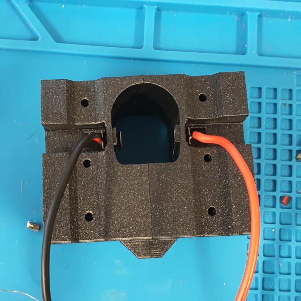
There are more pictures of this step in the Battery stud assembly discussion thread.
Note that the two halves of the battery stud are not symmetric.
- Identify the battery-stud half that mates with the positive pole of the battery
- Identify the battery-stud half that mates with the negative pole of the battery
- Make a red power cable go through the hole of the positive battery stud half, then solder a battery spring to it
- Repeat the process with a black power cable go through the other half
- Push the two battery springs into place (their flat parts should be flush with the 3D printed part, like so)
- Solder the red and black cable into the XT90-S connector
- Insert two M3x5x4 heat-set inserts in the corresponding holes of each battery stud half
- Use two M3x8 screws to assemble the two battery stud halves together
2.4) Heat-set inserts
Check out Threading 3D Printed Parts: How To Use Heat-Set Inserts if it is your first time with heat-set inserts. Once you're ready, proceed to insert them into the following parts:
| Part | Qty | Insert type (screw x OD x depth) | Number of inserts / part | Total num. of inserts |
|---|---|---|---|---|
| Battery stud left | 1 | M3x5x4 | 1 | 1 |
| Battery stud right | 1 | M3x5x4 | 1 | 1 |
| Back covers | 2 | M2.5x4x4 | 5 | 10 |
| Bottom plate | 1 | M2.5x4x4 | 4 | 1 |
| Femur | 2 | M3x5x4 | 4 | 8 |
| Head plate | 1 | M2.5x4x4 | 4 | 4 |
| Side plate | 2 | M3x5x4 | 26 | 52 |
| Tibia | 2 | M3x5x4 | 4 | 8 |
Ask questions about this step in Hardware discussions.
Previous: 1) Getting started — Next: 3) Raspberry Pi setup