Table of Contents
Spines compute observation dictionaries from sensor measurements by applying observers one after the other in a sequence called the observer pipeline. This page lists the outputs of available observers, using shorthands a.b.c for nested dictionary keys observation["a"]["b"]["c"].
Base orientation
- Observer: BaseOrientation
- Spine observation key:
base_orientation
The base orientation observer estimates the orientation of the floating base with respect to the world frame.
| Observation key | Description |
|---|---|
angular_velocity | Body angular velocity vector of the base frame in rad/s |
pitch | Pitch angle of the base frame relative to the world frame, in radians |
rotation_base_to_world | Rotation matrix from the base frame to the world frame |
Floor contact
- Observer: FloorContact
- Spine observation key:
floor_contact
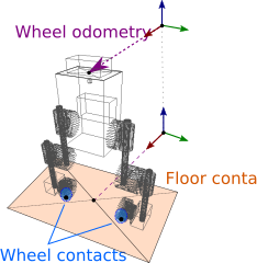
The floor contact observer detects contact between the wheels and the floor. The PID balancer used for testing relies on this observer, for instance, to reset its integrator while the robot is in the air, to avoid fast-spinning wheels at touchdown.
| Observation key | Description |
|---|---|
contact | Boolean contact state |
left_wheel | Wheel contact observation for the left wheel |
right_wheel | Wheel contact observation for the right wheel |
upper_leg_torque | Mean squared upper-leg torques in N⋅m |
Wheel contact
- Observer: WheelContact
- Spine observation key:
floor_contact.left_wheelandfloor_contact.right_wheel
Internally, the floor contact observer relies on two wheel contact observers, one for each wheel, as listed above.
| Observation key | Description |
|---|---|
abs_acceleration | Low-pass filtered absolute wheel acceleration in rad/s² |
abs_torque | Low-pass filtered absolute wheel torque in N⋅m |
contact | Current contact state (boolean) |
| inertia | Apparent inertia I = |torque| / |acceleration| at the wheel |
History observer
- Observer: HistoryObserver
- Spine observation key: - (optional)
The history observer reports higher-frequency signals from the spine as vectors of observations to lower-frequency agents. It handles floating-point and vector-valued observations. For instance, to report the left-knee torque readings on an Upkie, create a shared-pointer as follows and add it to the observer pipeline of the spine:
The same syntax can be used for a vector like the IMU linear acceleration:
IMU
- Observer: always reported
- See also: ImuData
- Spine observation key:
imu
| Observation key | Description |
|---|---|
angular_velocity | Body angular velocity of the IMU frame in rad/s |
linear_acceleration | Linear acceleration of the IMU, with gravity filtered out, in m/s² |
orientation | Orientation of the IMU frame in the ARS frame as a unit quaternion (w, x, y, z) |
raw_angular_velocity | Raw angular velocity measured by the gyroscope of the IMU, in rad/s |
raw_linear_acceleration | Raw linear acceleration measured by the accelerometer of the IMU, in m/s² |
The inertial measurement unit (IMU) mounted on the pi3hat combines an accelerometer and a gyroscope. These raw measurements are converted onboard by an unscented Kalman filter (based on a standard quasi-static assumption) that outputs observed quantities with respect to an attitude reference system (ARS) frame.
There are three main frames to keep in mind when considering the IMU: the frame of the IMU sensor itself, the world frame, and the attitude reference system (ARS) frame. The world frame is an inertial frame of reference we refer to in various observers. It has an x-axis pointing forward, a y-axis pointing to the left and a z-axis vertical and pointing up (i.e., against the gravity vector).
Servo
- Observer: always reported
- Spine observation key:
servo
| Observation key | Description |
|---|---|
<servo_name> | Observations for a given servo, *e.g. left_hip |
<servo_name>.position | Angle between the stator and the rotor in radians |
<servo_name>.torque | Joint torque in N⋅m |
<servo_name>.velocity | Angular velocity of the rotor w.r.t. stator in rotor, in rad/s |
Actuators on the robot are qdd100 beta 3 (hips and knees) and mj5208 brushless motors (wheels). All of them have moteus controller boards that provide the above measurements. They are estimated as follows:
- Joint angle, sensed by two orthogonal Hall-effect sensors at the back of the moteus controller board (each measuring the magnetic field in one direction; the output angle is then the arc-tangent of the ratio between these two values)
- Joint velocity, obtained by filtering joint angle measurements (not a direct measurement)
- Joint torque, estimated from sensed phase currents (with a model that includes stator magnetic saturation)
Simulation-only
- Observer: when using a simulation interface
- Spine observation key:
sim
Simulation spines may report the following additional observations.
Floating base
- Spine observation key:
sim.base
Positions and velocities of the base frame:
| Observation key | Description |
|---|---|
position | Position of the base frame in the world frame, in meters |
orientation | Unit quaternion (q, x, y, z) of the orientation of the base frame in the world frame |
linear_velocity | Linear velocity from base to world in world, in m/s |
angular_velocity | Angular velocity from base to world in world, in rad/s |
IMU non-observables
- Spine observation key:
sim.imu
Non-observable quantities related to the IMU:
| Observation key | Description |
|---|---|
linear_velocity | Linear velocity of the IMU frame in the world frame, in m/s |
Rigid bodies
- Spine observation key:
sim.bodies
Coordinates of some rigid bodies in the world frame:
| Observation key | Description |
|---|---|
YYY | Positions and velocities of the extra body YYY |
YYY.position | Position of YYY in the world frame, in meters |
YYY.orientation | Unit quaternion (q, x, y, z) of the orientation of YYY in the world frame |
Wheel odometry
- Observer: WheelOdometry
- Spine observation key:
wheel_odometry
This observer measures the relative motion of the robot with respect to the floor, outputting ground position and velocity estimates. These quantities are used for instance in the PID balancer, which tries to stay around the same spot on the floor.
| Observation key | Description |
|---|---|
position | Ground position in meters |
velocity | Ground velocity in m/s |